A Differential Op-Amp Circuit Collection - Parte III
4 Driving Differential Input Data Converters
Most high-resolution, high-accuracy data converters utilize differential inputs instead of singleended inputs. There are a number of strategies for driving these converters from single-ended inputs.

In Figure 14, one amplifier is used in a noninverting configuration to drive a transformer primary. The secondary of the transformer is center tapped to provide a common-mode connection point for the A/D converter Vref output.

Gain can be added to the secondary side of the transformer. In Figure 15, two single-ended op amps have been configured as inverting gain stages to drive the A/D Inputs. The non-inverting input inputs are connected to the transformer center tap and A/D Vref output.

Figure 16 shows how single-ended amplifiers can be used as noninverting buffers to drive the input of an A/D. The advantage of this technique is that the unity gain buffers have exact gains, so the system will be balanced.
Transformer interfacing methods all have one major disadvantage:
* The circuit does not include dc in the frequency response. By definition, the transformer isolates dc and limits the ac response of the circuit.
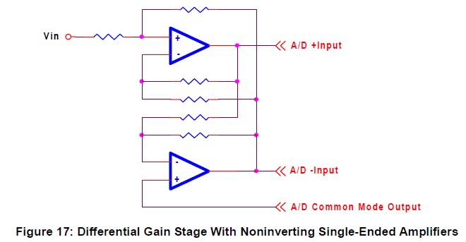
If the response of the system must include dc, even for calibration purposes, a transformer is a serious limitation. A transformer is not strictly necessary. Two single-ended amplifiers can be used to drive an A/D converter without a transformer:
If the response of the system must include dc, even for calibration purposes, a transformer is a serious limitation. A transformer is not strictly necessary. Two single-ended amplifiers can be used to drive an A/D converter without a transformer:
Although all of the methods can be employed, the most preferable method is the use a fully differential op-amp:

A designer should be aware of the characteristics of the reference output from the A/D converter. It may have limited drive capability, and / or have relatively high output impedance. A high-output impedance means that the common mode signal is susceptible to noise pickup. In these cases, it may be wise to filter and/or buffer the A/D reference output:

Some A/D converters have two reference outputs instead of one. When this is the case, the designer must sum these outputs together to create a single signal as shown in Figure 20:

No hay comentarios:
Publicar un comentario